Data Communication and Computer Network
A complete notes on Data Communication and Computer Network for loksewa, BIM and BCA students. Topics: Overview of network,LAN,WAN,MAN, Bus topology,star topology,ring topology,guided media,coaxial cable,data,communication,half duplex,full duplex, network protocols,tcp ip protocols, application, osi models,centralized system,distributed system

Data Communication and Computer Network
Introduction to communication system:
A communications system is an integrated system of communications hardware and software. This can include transmissions equipment, relay stations, tributary stations and other data terminal equipment. A communications system can even include other communications systems.
A good example would be a regional emergency response communications system that connects several different cities and allows them to respond to a disaster by integrating systems they have installed for their own police and firefighters.
Communications systems can include optical communications networks such as fiber-optic cables, radio and even power line communications. A sophisticated system might mix and match these different types of media.
There are two fundamental types of data communication, which transfer data in the communication system are:
- Voice Communication
- Data Communication
Voice Communication:
The voice communication system required individuals to speak in to a receiver/transmitter, which transmits the voice as a signal to another receiver/transmitter. This kind of communication system is available since invention of telephone, and is still use widely today. It propagates the analog signal.
Data Communication:
The world of the internet and email created a new type of communication system, which relies on the use of data transmission. Computer produces digital data that is binary, either on or off, 0 or 1. Data can be converts from one form into another and created as a packet for transmission over network circuit.
Mode of Communication:
Transmission mode means transferring of data between two devices, which is also known as communication mode. Buses and networks are designed to allow communication to occur between individual devices that are interconnected. There are three types of transmission mode:-
- Simplex Mode
- Half-Duplex Mode
- Full-Duplex Mode
Simplex Mode
In Simplex mode, the communication is unidirectional, as on a one-way street. Only one of the two devices on a link can transmit, the other can only receive. The simplex mode can use the entire capacity of the channel to send data in one direction.
Example: Keyboards and traditional monitors, the keyboard can only introduce the input. the monitor can only give the output.
Half-Duplex Mode
In half-duplex mode, each station can both transmit and receive, but not at the same time. When one device is sending, the other can only receive, and vice versa. The half-duplex mode is used in cases where there is no need for communication in both directions at the same time. The entire capacity of the channel can be utilized for each direction.
Example: Walkie-talkie in which message is sent one at a time and messages are sent in both the directions.
Full-Duplex Mode
In full-duplex mode, both stations can transmit and receive simultaneously. In full-duplex mode, signals going in one direction share the capacity of the link with signals going in other direction, this sharing can occur in two ways:
- Either the link must contain two physically separate transmission paths, one for sending and other for receiving.
- Or the capacity is divided between signals travelling in both directions.
Full-duplex mode is used when communication in both directions is required all the time. The capacity of the channel must be divided between the two directions. Example: Telephone Network, The communication between two persons by a telephone line, through which both can talk and listen at the same time.
Introduction to computer network:
A computer network is a group of computer systems and other computing hardware devices that are linked together through communication channels to facilitate communication and resource sharing among a wide range of users.
One of the earliest examples of a computer network was a network of communicating computers that functioned as part of the U.S. military's Semi-Automatic Ground Environment (SAGE) radar system. In 1969, the University of California at Los Angeles, the Stanford Research Institute, the University of California at Santa Barbara and the University of Utah were connected as part of the Advanced Research Projects Agency Network (ARPANET) project. This network now we call the internet.
Networks are used to:
- Facilitate communication via email, video conferencing, instant messaging, etc.
- Enable multiple users to share a single hardware device like a printer or scanner.
- Enable file sharing across the network.
- Allow for the sharing of software or operating programs on remote systems.
- Make information easier to access and maintain among network users.
Types of Computer Network:
A computer network is a group of computers linked to each other that enables the computer to communicate with another computer and share their resources, data, and applications.
A computer network can be categorized by their size. A computer network is mainly of three types:
- LAN(Local Area Network)
- MAN(Metropolitan Area Network)
- WAN(Wide Area Network)
LAN (Local Area Network)
Local Area Network is a group of computers connected to each other in a small area such as building, office. LAN is used for connecting two or more personal computers through a communication medium such as twisted pair, coaxial cable, etc. It is less costly as it is built with inexpensive hardware such as hubs, network adapters, and Ethernet cables. The data is transferred at an extremely faster rate in Local Area Network. Local Area Network provides higher security.
Fig: LAN
MAN (Metropolitan Area Network)
A metropolitan area network is a network that covers a larger geographic area by interconnecting a different LAN to form a larger network. Government agencies use MAN to connect to the citizens and private industries. In MAN, various LANs are connected to each other through a telephone exchange line. It has a higher range than LAN.

Fig: MAN
WAN (Wide Area Network)
A Wide Area Network is a network that extends over a large geographical area such as states or countries. A Wide Area Network is quite bigger network than the LAN. A Wide Area Network is not limited to a single location, but it spans over a large geographical area through a telephone line, fiber optic cable or satellite links. The internet is one of the biggest WAN in the world. It is widely used in the field of Business, government, and education.
Fig: WAN
Network Topologies:
Network Topology is the representation of a network arrangement, consisting of several nodes i.e. sender and receiver nodes, and the lines connecting these nodes. Types of network topologies are describe below:
- Bus Topology
- Ring Topology
- Star Topology
- Mesh Topology
- Tree Topology
- Hybrid Topology
Bus Topology
Bus topology is the kind of network topology where every node, i.e. every device on the network is connected to a solo main cable line. Data is transmitted in a single route, from one point to the other. We cannot transmit data in both ways. When this topology has precisely two endpoints, it is known as Linear Bus Topology. It is mostly used for small networks.

Fig: Bus Topology
Ring Topology
Ring Topology is a type of topology in which every computer is connected to another computer on each side, with the last computer being connected to the first, thus forming a ring shape. This topology allows for each computer to have exactly two neighboring computers.

Fig: Ring Topology
Star Topology
Star Topology is the kind of network topology in which all the nodes are connected via cables to a single node called hub, which is the central node. The hub can be active or passive in nature. Active hubs contain repeaters, while passive hubs are considered as non-intelligent nodes. Each node contains a reserved connection to the central node, which the central node acting as a repeater during data transmission.
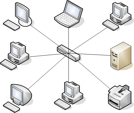
Fig: Star Topology
Mesh Topology:
Mesh topology is the kind of topology, in which all the nodes are connected with all the other nodes via a network channel. Mesh topology is a point-to-point connection.

Fig: Mesh Topology
Tree Topology:
Tree topology is the kind of topology in which the nodes are connected in a hierarchical manner, with all the nodes being connected to the topmost node or root node. Hence, it is also known as hierarchical topology. Tree topology has at least three levels of hierarchy.
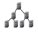
Fig: Tree Topology
Hybrid Topology:
Hybrid Topology is basically a network topology comprising of two or more different types of topologies. It is a reliable and scalable topology, but simultaneously, it is a costly one. It receives the merits and demerits of the topologies used to build it.

Fig: Hybrid Topology
Transmission Media:
Communication media refers to the means of delivering and receiving data or information. In telecommunication, these means are transmission and storage tools or channels for data storage and transmission. Communication media may be with wired or wireless. In wired signal travels along the cable from one device to another. But in wireless transmission the electromagnetic waves are transmitted without using physical wire or conductor.
Guided Media:
In guided media, transmitted data travels through cabling system that has a fixed path. For example, copper wires, fibre optic wires, etc.
The most popular guided transmission media are described below:
Twisted Pair Cable:
Copper wires are the most common wires used for transmitting signals because of good performance at low costs. They are most commonly used in telephone lines.
However, if two or more wires are lying together, they can interfere with each other’s signals. To reduce this electromagnetic interference, pair of copper wire is twisted together in helical shape like a DNA molecule. The advantage of twisting is that both wires are equally affected by external influences and unwanted signals are cancelled out.
Up to 25 twisted pairs are put together in a protective covering to form twisted pair cables that are the backbone of telephone systems and Ethernet networks.
Twisted pair is two types
Shielded Twisted Pair (STP): each pair is wrapped with an additional metal shield, then, all pairs are wrapped in a single outer plastic sheath.
Unshielded Twisted Pair (UTP): all pairs are wrapped in a single plastic cover.


Fig: UTP and STP twisted pair cable
Coaxial Cable:
Coaxial cables are copper cables with better shielding than twisted pair cables, so that, transmitted signals may travel longer distances at higher speeds. A coaxial cable consists of these layers, starting from the innermost −
- Stiff copper wire as core
- Insulating material surrounding the core
- Closely woven braided mesh of conducting material surrounding the insulator
- Protective plastic sheath encasing the wire which is outside insulation. Coaxial cables are widely used for cable TV connections and LANs.

Fig: Coaxial Cable
Optical Fiber:
Thin glass or plastic threads used to transmit data using light waves are called optical fiber. Light Emitting Diodes (LEDs) or Laser Diodes (LDs) emit light waves at the source, which is read by a detector at the other end. Optical fiber cable has a bundle of such threads or fiber bundled together in a protective covering. Each fiber is made up of these three layers, starting with the innermost layer:
- Core made of high quality silica glass or plastic
- Cladding made of high quality silica glass or plastic, with a lower refractive index than the core
- Protective outer covering called buffer
Note that both core and cladding are made of similar material. However, as refractive index of the cladding is lower, any stray light wave trying to escape the core is reflected back due to total internal reflection.
Unguided Media:
In unguided media, transmitted data travels through free space in form of electromagnetic signal. For example, radio waves, lasers, etc.
Following are the example of unguided media.
Microwave System:
Microwave transmission is the line of sight transmission. The transmit station must be in visible contact with the receiver station. This sets a limit on the distance between stations depending on the local geography. Typically, the line of sight due to earth’s curvature is only 50 km to the horizon. So, the repeater station should be placed on this distance. It is relatively inexpensive, putting up two tower and antennas for each is cheaper then 50 km ling fiber cable.
Example of microwave system is mobile phone network, television distribution etc.
![]()
Fig: Microwave system
Here in this figure we can see, Station A sends the voice data to the Repeater site 1 with 1.2 GHz frequency. Then Repeater Site 1 sends data to another tower with 10 GHz frequency which forwards that data to Repeater Site 2. And finally Repeater Site 2 sends that data to the Station C with 1.2 GHz frequency.
Communication Satellites:
It is also a kind of line of sight transmission. Satellite stations are set in geo-stationary orbits directly cover the equator, which rotates in synchronization to earth and hence look stationary from any point on the earth. Those geo-stationary orbits are placed 36,000 km above the earth’s surface. The communication is carried through uplink and downlink. The uplink transmits the data to the satellite and downlink received the data from satellite. The area shadowed by the satellite in which the information or data can be transmitted and received is called footprint.
Communications satellites are commonly used for mobile phone signals, weather tracking, or broadcasting television programs.

Fig: Communication Satellite System
Here in the figure we can see that, Transmitting dish antenna in the transmitting earth station sends the data to satellite using uplink frequency. When satellite received the data then it send those data to receiving dish antenna in the receiving earth station using downlink frequency.
Infrared:
An infrared transmission is a wireless technology used for communication over short range. The frequency of the infrared is in the range from 300 GHz to 400 THz. It is used for short-range communication such as data transfer between two cell phones, TV remote operation, data transfer between a computer and cell phone resides in the same closed area.
Network Devices:
- Repeater
A repeater operates at the physical layer. Its job is to regenerate the signal over the same network before the signal becomes too weak or corrupted so as to extend the length to which the signal can be transmitted over the same network. An important point to be noted about repeaters is that they do not amplify the signal. When the signal becomes weak, they copy the signal bit by bit and regenerate it at the original strength. It is a 2 port device.
- Hub
A hub is basically a multiport repeater. A hub connects multiple wires coming from different branches, for example, the connector in star topology which connects different stations. Hubs cannot filter data, so data packets are sent to all connected devices. In other words, collision domain of all hosts connected through Hub remains one. Also, they do not have intelligence to find out best path for data packets which leads to inefficiencies and wastage.
Types of Hub
Active Hub:- These are the hubs which have their own power supply and can clean, boost and relay the signal along with the network. It serves both as a repeater as well as wiring centre. These are used to extend the maximum distance between nodes.
Passive Hub:- These are the hubs which collect wiring from nodes and power supply from active hub. These hubs relay signals onto the network without cleaning and boosting them and can’t be used to extend the distance between nodes.
- Bridge
A bridge operates at data link layer. A bridge is a repeater, with add on the functionality of filtering content by reading the MAC addresses of source and destination. It is also used for interconnecting two LANs working on the same protocol. It has a single input and single output port, thus making it a 2 port device.
Types of Bridges
Transparent Bridges:- These are the bridge in which the stations are completely unaware of the bridge’s existence i.e. whether or not a bridge is added or deleted from the network, reconfiguration of the stations is unnecessary. These bridges make use of two processes i.e. bridge forwarding and bridge learning.
Source Routing Bridges:- In these bridges, routing operation is performed by source station and the frame specifies which route to follow. The hot can discover frame by sending a special frame called discovery frame, which spreads through the entire network using all possible paths to destination.
- Switch
A switch is a multiport bridge with a buffer and a design that can boost its efficiency(a large number of ports imply less traffic) and performance. A switch is a data link layer device. The switch can perform error checking before forwarding data, that makes it very efficient as it does not forward packets that have errors and forward good packets selectively to correct port only. In other words, switch divides collision domain of hosts, but broadcast domain remains same.

- Routers
A router is a device like a switch that routes data packets based on their IP addresses. Router is mainly a Network Layer device. Routers normally connect LANs and WANs together and have a dynamically updating routing table based on which they make decisions on routing the data packets. Router divide broadcast domains of hosts connected through it.

- Gateway
A gateway, as the name suggests, is a passage to connect two networks together that may work upon different networking models. They basically work as the messenger agents that take data from one system, interpret it, and transfer it to another system. Gateways are also called protocol converters and can operate at any network layer. Gateways are generally more complex than switch or router.
- Brouter
It is also known as bridging router is a device which combines features of both bridge and router. It can work either at data link layer or at network layer. Working as router, it is capable of routing packets across networks and working as bridge, it is capable of filtering local area network traffic
OSI Reference Model:
The Open Systems Interconnection (OSI) model is a conceptual model created by the International Organization for Standardization, which enables diverse communication systems to communicate using standard protocols. In plain English, the OSI provides a standard for different computer systems to be able to communicate with each other.
The OSI model can be seen as a universal language for computer networking. It’s based on the concept of splitting up a communication system into seven abstract layers, each one stacked upon the last.
Each layer of the OSI model handles a specific job and communicates with the layers above and below itself.
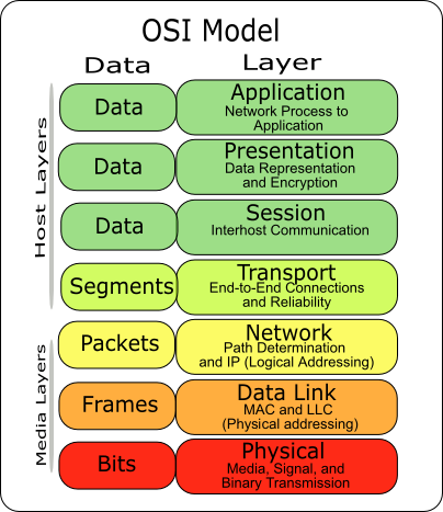
- The Application Layer
This is the only layer that directly interacts with data from the user. Software applications like web browsers and email clients rely on the application layer to initiate communications. The application layer is responsible for the protocols and data manipulation that the software relies on to present meaningful data to the user.
Application layer protocols include HTTP as well as SMTP (Simple Mail Transfer Protocol is one of the protocols that enables email communications).
- The Presentation Layer
This layer is primarily responsible for preparing data so that the application layer can use it. The presentation layer is responsible for translation, encryption, and compression of data.
Two communicating devices may be using different encoding methods, so layer 6 is responsible for translating incoming data into a syntax that the application layer of the receiving device can understand.
Finally, the presentation layer is also responsible for compressing data it receives from the application layer before delivering it to layer 5. This helps improve the speed and efficiency of communication by minimizing the amount of data that will be transfer.
- The Session Layer
This is the layer responsible for opening and closing communication between the two devices. The time between when the communication is opened and closed is known as the session. The session layer ensures that the session stays open long enough to transfer all the data being exchanged, and then promptly closes the session in order to avoid wasting resources.
The session layer also synchronizes data transfer with checkpoints. For example, if a 100 MB file is being transferred, the session layer could set a checkpoint every 5 MB. In the case of a disconnect or a crash after 52 MB have been transferred, the session could be resumed from the last checkpoint, meaning only 50 more MB of data need to be transferred. Without the checkpoints, the entire transfer would have to begin again from scratch.
- The Transport Layer
Layer 4 is responsible for end-to-end communication between the two devices. This includes taking data from the session layer and breaking it up into chunks called segments (it contains original data with acknowledgement of another segment wrapped by header with different controls like source port, destination port, flags, checksum, sequence number) before sending it to layer 3. The transport layer on the receiving device is responsible for reassembling the segments into data the session layer can consume.
The transport layer is also responsible for flow control and error control. Flow control determines an optimal speed of transmission to ensure that a sender with a fast connection doesn’t overwhelm a receiver with a slow connection. The transport layer performs error control on the receiving end by ensuring that the data
received is complete, and requesting a retransmission of it.
- The Network Layer
The network layer is responsible for facilitating data transfer between two different networks. If the two devices communicating are on the same network, then the network layer is unnecessary. The network layer breaks up segments from the transport layer into smaller units, called packets (it contains segment with extra adding source and destination IP address, Time-to-Live, and Identification), on the sender’s device, and reassembling these packets on the receiving device. The network layer also finds the best physical path for the data to reach its destination; this is known as routing.
- The Data Link Layer
The data link layer is very similar to the network layer, except the data link layer facilitates data transfer between two devices on the SAME network. The data link layer takes packets from the network layer and breaks them into smaller pieces called frames (it contains packets along with frame header including source MAC address, destination MAC address, and checksum). Like the network layer, the data link layer is also responsible for flow control and error control in intra-network communication (The transport layer only does flow control and error control for inter-network communications).
- The Physical Layer
This layer includes the physical equipment involved in the data transfer, such as the cables and switches. This is also the layer where the data gets converted into a bit stream, which is a string of 1s and 0s. The physical layer of both devices must also agree on a signal convention so that the 1s can be distinguished from the 0s on both devices.
Communication Protocols:
In telecommunication, a communication protocol is a system of rules that allow two or more entities of a communications system to transmit information via any kind of variation of a physical quantity. The protocol defines the rules, syntax, semantics and synchronization of communication and possible error recovery methods. Protocols may be implemented by hardware, software, or a combination of both.
Communicating systems use well-defined formats for exchanging various messages. Each message has an exact meaning intended to elicit a response from a range of possible responses pre-determined for that particular situation. The specified behavior is typically independent of how it is to be implemented. Communication protocols have to be agreed upon by the parties involved. To reach an agreement, a protocol may be developed into a technical standard.
Centralized Vs Distributed System:
Centralized System
We start with centralized systems because they are the most intuitive and easy to understand and define.
Centralized systems are systems that use client/server architecture where one or more client nodes are directly connected to a central server. This is the most commonly used type of system in many organizations where client sends a request to a company server and receives the response.
Fig: Centralized system
Example: Wikipedia, Consider a massive server to which we send our requests and the server responds with the article that we requested. Suppose we enter the search term ‘junk food’ in the Wikipedia search bar. This search term is sent as a request to the Wikipedia servers (mostly located in Virginia, U.S.A) which then responds back with the articles based on relevance. In this situation, we are the client node, Wikipedia servers are central server.
Advantages of Centralized System
- Easy to physically secure. It is easy to secure and service the server and client nodes by virtue of their location
- Smooth and elegant personal experience – A client has a dedicated system which he uses(for example, a personal computer) and the company has a similar system which can be modified to suit custom needs
- Dedicated resources (memory, CPU cores, etc)
- More cost efficient for small systems upto a certain limit – As the central systems take less funds to set up, they have an edge when small systems have to be built
- Quick updates are possible – Only one machine to update.
- Easy detachment of a node from the system. Just remove the connection of the client node from the server and voila! Node detached.
Disadvantages of Centralized System
- Highly dependent on the network connectivity – System can fail if the nodes lose connectivity as there is only one central node.
- No graceful degradation of system – abrupt failure of the entire system
- Less possibility of data backup. If the server node fails and there is no backup, you lose the data straight away
- Difficult server maintenance – There is only one server node and due to availability reasons, it is inefficient and unprofessional to take the server down for maintenance. So, updates have to be done on-the-fly(hot updates) which is difficult and the system could break.
Distributed Systems:
A distributed system contains multiple nodes that are physically separate but linked together using the network. All the nodes in this system communicate with each other and handle processes in tandem. Each of these nodes contains a small part of the distributed operating system software.
It consists of autonomous computers that are connected using a distribution middleware. They help in sharing different resources and capabilities to provide users with a single and integrated coherent network.
Fig: Distributed system
Example: Google search system. Each request is worked upon by hundreds of computers which crawl the web and return the relevant results. To the user, the Google appears to be one system, but it actually is multiple computers working together to accomplish one single task (return the results to the search query).
Advantages of distributed operating systems
- Give more performance than single system
- If one pc in distributed system malfunction or corrupts then other node or pc will take care of
- More resources can be added easily
- Resources like printers can be shared on multiple pc’s
Disadvantages of distributed operating systems
- Security problem due to sharing
- Some messages can be lost in the network system
- Bandwidth is another problem if there is large data then all network wires to be replaced which tends to become expensive
- Overloading is another problem in distributed operating systems
- If there is a database connected on local system and many users accessing that database through remote or distributed way then performance become slow
- The databases in network operating is difficult to administrate then single user system
By Lec. Pratik Chand, Morgan Int’l College


