Introduction to Digital Logic
1.1 Digital Signals and Waveforms
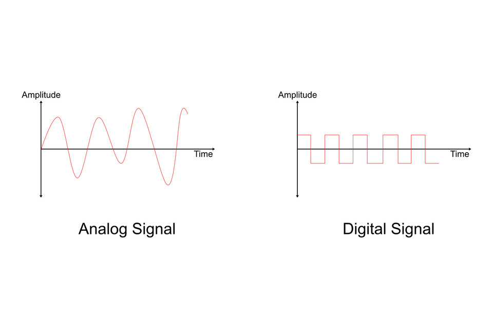
- Electronic circuits and systems can be conveniently divided into two broad categories generally referred as analog and digital signals.
- Any quantity that changes with time either can be represented as an analog signal or it can be treated as a digital signal.
- Digital electronics involves quantities with discrete values, & analog electronics involves quantities with continuous values.
- The quantity that has continuous values is called as the analog quantity.
- Examples of analog quantities are time, temperature, pressure, distance, and sound.
- The quantity that has a discrete set of values is called as the digital quantity. It is represented by 1 or 0.
Advantages of Digital Quantities over Analog
- Digital data can be processed and transmitted more efficiently.
- It can store huge amount of data at lesser space and with least chances of errors.
- Noise does not affect digital data as compared to analog signals.
- The transmission is more secure with encryption.
- Signals are used to carry information from one device to another. Analog and Digital are the different forms of signals.
- Analog and digital signals are used to transmit information (such as any audio or video), usually through electric signals.
Digital Waveform:
Digital waveform consists of voltage levels that are changing back and forth between the HIGH and LOW levels as states.
The following are the characteristic of digital waveform:
- Rise Time:
The time required for the pulse to go from its low level to its high level is called rise time(tr).It is common to measure rise time from 10% of the pulse amplitude to 90% of pulse amplitude. - Fall Time:
It is the time required for the transition form high level to low level . It is time form 90% to 10% of amplitude. - Time period:
It is time over which a signal repeats itself. - Frequency:
It is rate at which signal repeats itself. - Duty Cycle:
It is ratio of the pulse width(tw) to the period and can be expressed as percentage.
Duty cycle for H= th/T *100%
Duty cycle for L= tL/T *100%
1.2 Digital Logic and Operation
- Logic means certain declarative statement which is true if certain conditions are fulfilled and false if that condition is not meet.
- The manner in which the digital circuit responds to an input is referred to as circuit’s logic.
- Logic gates are building block of any digital system. It is an electronic circuit having one or more than one inputs and only one output.
- The relationship between the input and output is based on certain logic.
- Based on logic, the gates are named as NOT gate, AND gate, OR gate, NAND gate, NOR gate, etc.
- In the decimal system, which is used in our day-to-day life, the arithmetic operation such as addition, subtraction, multiplication , modulus, etc. are used to solve equations.
- Similarly to solve or simplify logical expressions, used in digital circuits, we need to use logical operators.
- The three main logic operators may be listed as:
- AND operator(A.B → logical multiplication)
- OR operator(A+B → logical addition)
- NOT operator(A' → logical inversion)
- The operation of logic gate is understood by the help of a table called “truth table”.
- The truth table consists of all the possible combinations of the inputs and the corresponding state of output of a logic gate.
- The relationship between the inputs and outputs of a gate can be expressed mathematically by help of Boolean Expression.
Logic gate can be classified into three categories:
- Basic Gates(NOT, AND , OR)
- Universal Gates(NAND, NOR)
- Derived Gates(Ex-OR, Ex-NOR)
1.3 Digital Computer and Integrated Circuits(IC)
- A digital IC is constructed by an interconnection of resistors, transistors, and capacitors, all of which have been formed on the surface of silicon wafer.
- The entire circuits resides on a tiny piece of semiconductor material called a chip.
- There are two digits in binary systems ‘1’ and ‘0’ which are called bits. This is called “binary digit”.
- In digital circuit, two different voltage level are used to represent the two bits.
- Generally, 1 is represented by the higher voltage, which is referred as HIGH, and
- 0 is represented by the lower voltage, which is referred as LOW. This is called positive logic.
- In another system, ‘1’ is represented by LOW and ‘0’ is represented by HIGH. This system is said to be Negative Logic.
- The voltage used to represent ‘1’ & ‘0’ are called logic levels.
- Particularly, High is voltage between specified minimum value and maximum value, and
- Low is the voltage between specified minimum and maximum value. There is no overlap between HIGH levels and LOW levels.
Nowadays, the majority of digital circuit families utilizes a single +5V DC power supply, and the two
Voltage levels used are +5V DC and 0V DC.
Digital Computer
- A digital computer is a class of devices capable of solving problems by processing information in discrete form. It operates on data, including magnitudes, letters, and symbols, that are expressed in binary code—i.e., using only the two digits 0 and 1.
- Some of the basic examples of digital devices are Personal computers, Desktops, Laptops, Smartphones, and Mobiles.
- There are mainly three parts in a digital computerand it consists of
- Input: The user normally provides the data to the device that is known as input.
- Processing: The input that is provided by the user is processed internally using some defined sequence. CPU is the Central Processing Unit which is known as the brain of the computer as it controls the entire computer system. CPU has different components Arithmetic Logic Unit(ALU) , Control unit(CU), and Memory.
- Output: Once the processing is completed, based on the input, the output is displayed to the user.

Features of a digital computer
- Good Memory – Digital computers can store a large number of data and can retrieve data in a fraction of second. The data can be stored for any duration and retrieved anytime.
- Very Flexible – These computers can perform multi-tasking without any human interference and hence they are very flexible and versatile.
- Automatic – These devices once started are automatic. They do not need any intervention until required by the task specifically.
- Good Speed – Digital computers are high in speed and carry out all the operations with very fast speed.
- Accurate – These devices help in storing all the information which helps in retrieving accurate data at any point in a given time.
1.4 Clock Waveform
Waveforms are shapes and forms of signals. There are many different Types of them. The most common ones are the periodic signals,where time, wavelength, amplitude and phase are the main attributesthat define them.
We split them into:
- Sine Waves(that follow the amplitude of the trigonometric sine function)
- Square Waves(that periodically switch from a to b and vise versa, so that we have square shapes)
- Saw-tooth Waves (that periodically switch between a and b going only from a to b in a straight line directly and getting directly into a again or the opposite, forming a saw shape).
- Triangular Wave(that periodically switch between a and b and vise versa going in a straight line, so that it forms a triangle shape)

We can also have non periodic waveforms.
The device that prints out waveforms for a specific line in our Circuit is called Oscilloscope.